Microwave Frequency PCB
Microwave-frequency PCB integrating an oscillator, amplifier, and filter — designed and validated in the lab.
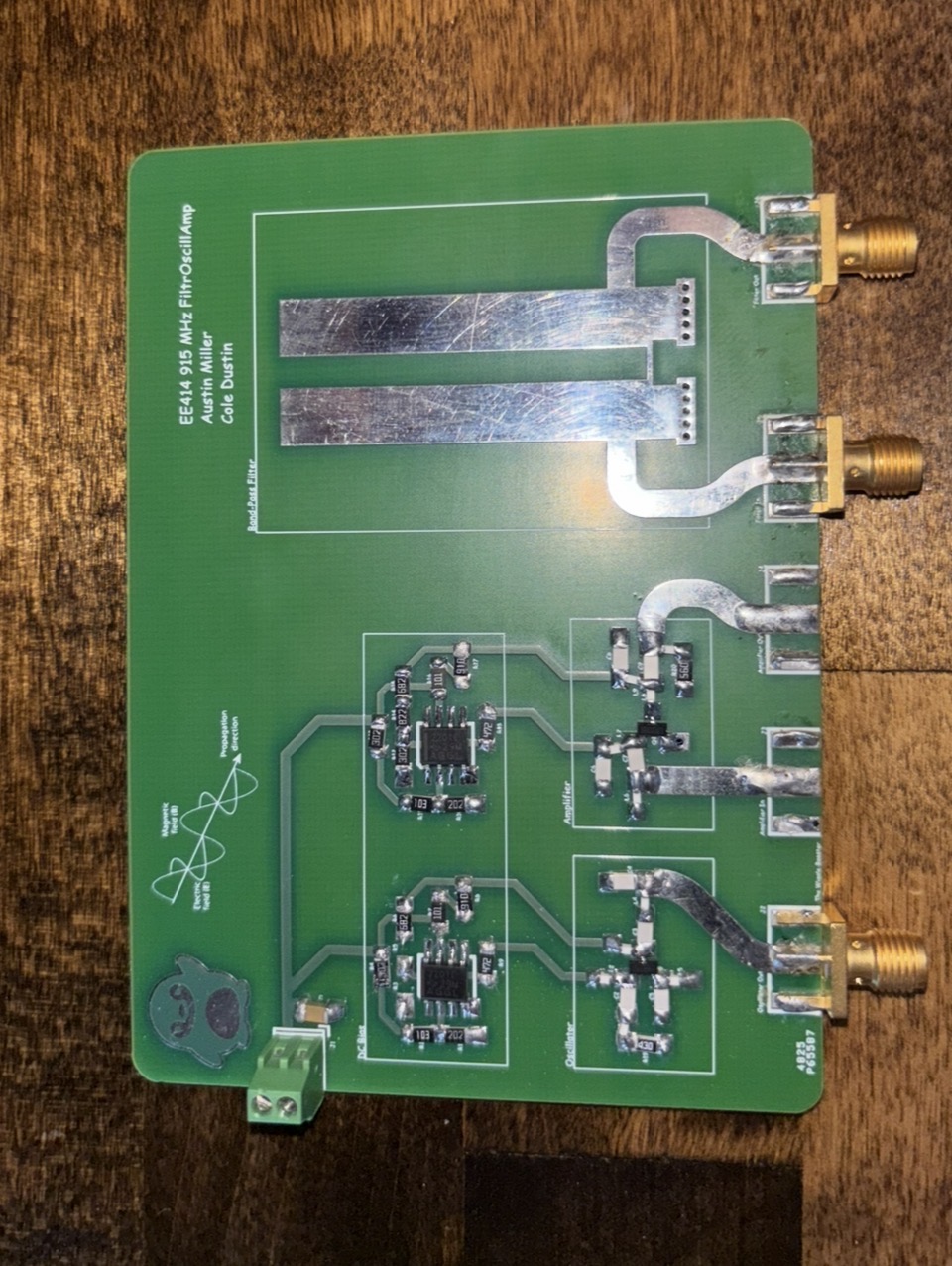
Hardware photo
Overview
- Designed a microwave-frequency PCB with an oscillator, amplifier, and filter stages.
- Iterated based on measurement feedback and parameter tuning.
- Add measured plots (S-parameters, spectrum, time-domain).
What I Built
- Microwave-frequency signal chain PCB (oscillator + amplifier + filter).
- Designed for lab measurement and iteration.
Testing & Results
I still need S-parameter plots, spectrum plots. Explain measurements (gain, bandwidth, noise, stability).
What I Learned
I learned that nothing is simple when designing an RF circuit, you have impedance matching, transmission line's have refelction and complex reactance, everything has parasitics. Making a cutout in transmission lines acts like a capacitor etc.. .